
System Memory:
Just as the movie ticket serves as a controlling agent between the demand and the seats in a theatre, similarly virtual memory are like tickets to processes that must occupy slots in the physical memory (RAM). If Physical Memory is running to full capacity, then the processes committed with a ticket in virtual memory will have to wait till some processes exits Physical Memory and makes room for the new processes to enter.
A process is essentially a set of tasks contained in a program, one or more of which executes through a sequence of instructions called threads. Processes run on the operating system and the operating system manages the hardware resources for all the running processes. The operating system provides a Virtual Memory to all processes which must run on Physical Memory. The address space of the virtual memory in bytes is (2^address bits), where the bits corresponds to the physical address lines in the system architecture (32 bit Or 64 bit). The address space of the physical memory depends on the amount of RAM installed. The virtual memory manager of the operating system applies a method called Paging to map the virtual address space to the physical address space, in such a way that all processes can get to run on the physical memory. If Physical memory is sufficiently large to accommodate all processes, then the committed virtual address space is mapped to physical address space at once. If Physical memory is less than the combined memory demand of all processes, then the virtual memory manager will have to load each process sequentially on the physical memory, wait for the process to end, and then rewrite a new process on the physical memory and repeats this till all processes committed to virtual memory are executed.

The operating system (OS) acts as a platform and interfaces all processes by its Virtual Memory, and on the other hand the OS gets to run these processes on the Hardware by mapping the processes in its Virtual Memory to the Physical Memory. This mandates all processes to be designed specific to an OS, thereby disallowing processes to directly communicate with the Hardware which remains shielded and under the sole control of the OS.
This renders the processes to become Platform Independent, meaning that processes designed for a particular OS will always work irrespective of the hardware platform on which the OS is installed.
The Virtual Memory manager of the operating system use special Paging techniques namely Disc Paging and Demand Paging to overcome the space limitation of Physical memory.
Disc Paging extends the computer’s physical memory (RAM) by reserving space on the hard disc called Page File which the processor views as non-volatile RAM. When there is not enough memory available in RAM to allocate to a new process, the virtual memory manager moves data from RAM to the Page file. Moving data to the Page file frees up RAM making room for the new process to complete its work. However, accessing data from the Page file degrades the system performance considerably. Disc Paging is of use only on systems with limited physical memory which would otherwise not allow a large process or multiple processes to run concurrently. Increasing virtual memory will not improve performance on such a system.
When a process references a virtual memory page that is on the disc, because it has been paged-out, the referenced page must be paged-in and this might cause one or more pages to be paged-out using a page replacement algorithm. If the CPU is continuously busy swapping pages, so much that it cannot respond to user requests, the computer session is likely to crash and such a state is called Thrashing. If thrashing occurs repeatedly, then the only solution is to increase the RAM.
The concept of disc paging evolved when systems had 256 MB or less memory. In modern systems with sufficient amount of memory ( ≥ 4GB), the use of Page file is limited to caching pre-fetched data. However with advent of mobile devices, Disc Paging is an attractive option to extend RAM with ultra-fast Solid State Drives.
Demand Paging is key to using the physical memory when a number of processes must run with a combined memory demand exceeding the available physical memory. This is achieved by segmenting the process into smaller tasks. Only the threads corresponding to a specific task are loaded to memory which are required for immediate processing, instead of allowing the entire process to get into the memory. Services that run in the background are typically threads of a larger process. The exception is the Graphics and Hardware Drivers for which memory is reserved and is not available to the Memory manager.
Windows Memory Representation
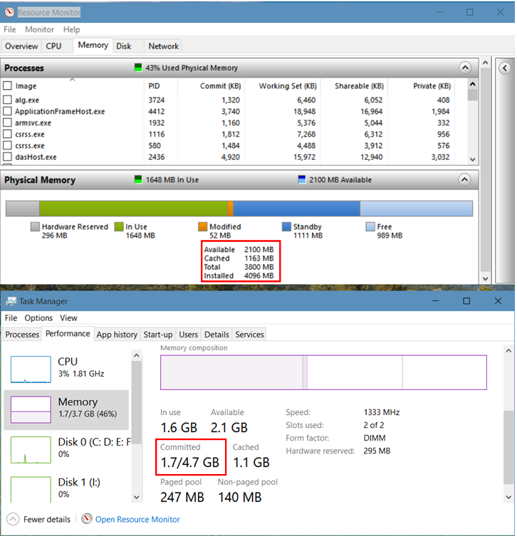
Resource Monitor and Task Manager screenshots
The amount of physical memory used by a process is called a Working Set. The Working Set of a process is comprised by its Private working set and its Sharable working set both of which are owned by the same process. The Private working set is the amount of physical memory in use pertaining to tasks that are dedicated to the process. The Sharable working set is the amount of physical memory in use by the process pertaining to tasks that can be shared with other processes.
Working Set of a process = Private Working Set + Sharable Working Set.
For example, when you open a Word document, the winword.exe remains in the Sharable working set and the contents of the document is put in Private working set. Thus several word documents opened simultaneously can share the same winword.exe while their data is private and distinct. Shared system resources such as DLLs, System drivers (Kernel/OS.sys files) exists solely as a Shared process with no private working set. Tasks and Services comprise the executable processes (.exe) which are primarily private working sets having a sharable resource.
The Commit and Working Set of all running processes can be viewed on the Memory tab of the Resource Monitor. The Commit is the amount of Virtual Memory reserved by the operating system for a particular process. This amount is only an estimation of the Page File size needed by a process, and is not allocated till it becomes necessary for the system to page out the Private working set of a process in physical memory to the Page File. It is for this reason, the Commit size is always larger than the Private working set of a process.
The sum of all process Commits therefore indicates the Virtual Memory demand by the system which needs to be met from the Page File. However, the Page File size can be configured much less than the Virtual Memory demand, as the system will essentially become non-functional if the private working sets of all running processes are to be paged out.
Virtual Memory or Page File size can be viewed/modified through System Properties > Advanced tab > Performance Settings > Advanced tab > Virtual Memory section (left screenshot, below). Perhaps the best decision is to allow the system to manage this for itself.
The modules in the Sharable working set are not shown in the Resource Monitor. You can view the list of running DLLs & System Drivers through System Information (Run > msinfo32) > Software Environment (left menu) > System Drivers (kernel & OS drivers) || Loaded modules (dlls) || Running Tasks (Processes as seen on Resource Monitor) || Services (contained in Running Tasks).
Tip: You can manually copy the entire Process list in the Memory tab of the Resource Monitor, and paste into an Excel Worksheet for your analysis. However these values keep changing rapidly and so cross-reference to the static memory values in System Information should be synchronised at the same point in time.
The Committed (1.7 GB) as seen on the Task Manager > Performance tab > Memory section, is the sum total of Working sets of all running processes + amount of data cached in Page file, or in other words the Virtual Memory in use.
Total Virtual Memory = Total Physical + Page File Size
= 3800 + 1024 = 4824 MB = 4.71 GB.
Total Virtual Memory is also referred to as Commit Size Limit.

Virtual Memory usage can be seen through System Information (Run > msinfo32), right screenshot above:
Total Virtual Memory = Committed (Virtual In Use) + Available Virtual Memory
Or, Committed (Virtual In Use) = Total Virtual – Available Virtual
= 4.71 GB – 2.96 GB
= 1.75 GB (as seen on Task Manager).
The Virtual Memory term in Windows is actually polymorphic. One terminology applies to memory representation where in the true technical sense, Virtual Memory = Physical memory + Page file, although the term Virtual Memory is more often used as a synonym to Page File.
Virtual Memory also refers to the Operating System's abstraction of memory into a process directory, where each folder is a collection of Pages (4KB segments) scattered in memory of a process working set, with the underlying page location data per process residing on a distinct Page Table. This Page Table is a sequential ordering of pages of a process working set, where pages are identified by their assigned index ranging from 0 upto 2^address bits, with each page index specifying the random location of the page in Physical Memory. This enables the OS software to sequentially index through the pages of a process and execute the codes by referring to the physical memory location of the page in the Page Table.
When a machine boots up, the operating system creates two dynamically sized pools in physical memory to allocate the kernel-mode components. These two pools are known as the Paged Pool and Non-paged Pool.
The Paged Pool value (247 MB, refer to Task Manager screenshot on top) indicates the amount of physical memory used by the Kernel to store objects that can be written to disc (paged) when they are no longer used.
The Non-paged Pool value (140 MB, refer to Task Manager screenshot on top) indicates the amount of physical memory used by the Kernel to store objects that cannot be written to disc but must remain in physical memory at all times.
Physical Memory:
Physical memory refers to actual RAM chips or modules, typically installed on a computer’s motherboard.
Hardware Reserved (296 MB) is the memory space reserved by hardware drivers which must be always remain on the RAM. This memory is essentially locked and is not available to the memory manager. A major part of this is the dedicated Graphics Memory reserved through BIOS.
In Use (1648 MB) memory is the sum total of Working Sets of all running processes owned by the operating system, kernel (non-paged pool), drivers and the various applications.
Modified (52 MB) memory contains modified pages that have been removed from process working sets, because it was idle for long. Modified memory contents must be written to disk before it can be repurposed. As such it is currently not in use but can still be quickly pulled into service if needed. If memory demand runs high or the modified list have grown beyond a certain threshold, the memory manager arranges to write pages from the modified memory to the page file on hard disc, and moves those pages from the Modified to the Free memory.
Standby (1111 MB): When a process exits normally, the memory manager moves the unmodified pages in the working set to the Standby memory, which effectively makes the Standby memory a true cache of recently used files. By keeping these pages on the Standby list, the memory manager reduces the need to re-fetch the information from web/disk/network location which is more involved and time consuming, should the pages be required again.
When a process requests for a page, the memory manager first looks for the page in the Standby memory and if available, returns it as a working set. This is called repurposing a page. If the page is not present in Standby, the memory manager loads it from the Hard Disk into the Free Memory which then becomes part of the process working set.
All pages on the Standby list are available for memory allocation requests. The memory pages in Standby list are prioritized in a range of 0-7, with 7 being the highest. When a process requests additional memory and there is not enough memory in the Free list, the memory manager takes a page with low priority from the Standby list, and releases it to the Free list for the new process to occupy.
The Free (989 MB) memory are the locations that have not yet been allocated to any process OR were previously allocated but returned to the memory manager for reuse when the process ended. All memory demand by the system is met from the Free memory.
The memory manager maintains a thread that wakes up periodically to initialize pages on the Free page list so that it can move them to the Zero page list. The Zero page list contains pages that have been initialized to zero, ready for use when the memory manager needs a new page.
Installed Physical Memory is the RAM installed = 4GB = 4096 MB.
Installed Memory = In Use + Modified + Standby + Free + Hardware Reserved
= 1648 + 52 + 1111 + 989 + 296 = 4096 MB.
If installed RAM is sufficiently greater than the Committed (peak value over time), then the system is unlikely to experience any memory constraint.
Total Physical Memory = Installed - Hardware Reserved = 4096 - 296 = 3800 MB.
This is the Usable memory available to the Memory Manager.
Cached Memory = Modified + Standby = 52 + 1111 = 1163 MB.
Cached memory holds data or program code that has been fetched into memory during the current session but is no longer in use now. If necessary, the Windows memory manager will flush the contents of cached memory and release it to the free memory.
Available Memory = Standby + Free = 1111 + 989 = 2100 MB.
Committed (Virtual In Use) = Physical Memory in Use + Page file in Use
Or, Page file in Use = Committed - Physical Memory in Use
= 1.75 GB - 1648 MB = 1792 -1648 = 144 MB.
Virtual Memory Organisation:
Every process needs a space in memory to store its data and codes. This is called the address space of a process. The original idea of virtual memory was to expand the physical memory with a reserved space in hard disc called Page file which the program would view as RAM and this was termed as Disc Paging. Subsequently the virtual memory concept was redefined so that processes run on the operating system and the operating system provides a Virtual Memory to all processes while it manages the physical memory on behalf of itself and all its processes. This virtual memory is limited only by the theoretical address space possible on the computer architecture, thus maximising the address space interface to a process. Virtual Memory also helped to establish memory protection by disallowing processes to directly address the physical memory which is unaware of other processes using the memory.
A process runs from the virtual memory provided by the operating system, while the CPU interfaces with the operating system to fetch and execute the instructions from the physical memory. The operating system maintains a translation table called Page Table ordered by the virtual memory addresses assigned to each process, having cross-reference to the physical memory addresses. The CPU incorporates a hardware logic to sequentially generate the same virtual addresses and gives it to its own Memory Management Unit (MMU), which refers to the Page Table and locates the physical address where the instruction is stored.
The Virtual Memory Manager (VMM) of the operating system manages the memory requests made by all processes. The VMM allocates consecutive address in the virtual memory in units called Page, to each process which must run. Initially each Page is initialized with the storage locations of the process files on hard disc which are subsequently replaced by the physical memory addresses once the process files are loaded to memory. This allows an operating system to provide an address space to all processes in the virtual memory, irrespective of the size of physical memory available.
The mapping of a Virtual Page to Physical memory occurs in units called Page frame which are of the same size of the Page and formed by consecutive bytes in physical memory. However, while Pages are continuous in Virtual memory, the corresponding Page frames are randomly distributed in Physical memory. A Page frame is an array of memory bytes and is essentially a higher unit of memory size, appropriate for allocating to processes. The collection of all page frames of a process comprises its Working Set.
Thus the operating system maintains a Page Table for each process, containing the process pages in virtual memory mapped either to its page frame in physical memory Or initialized to the page location on hard disc. Page Tables of all running processes are created on the physical memory at system start.
Each process can access the entire virtual address space (2^32 bytes Or 2^64 bytes) on its own without any restriction and so each process use the same set of virtual memory addresses for its pages. The virtual memory manager knows the process owning the page by the Page Table ID and will map them to separate page frames in physical memory. Conversely, multiple processes can individually own a shared process by defining pages in their respective Page Table, which map to the same page frames in physical memory.
A Page is a virtual entity and therefore its memory space has no physical existence. A Page exists only in the form of a page address on Page Table which is a physical entity. This Page Table is essentially the Virtual Memory and a Page is analogous to a ticket in virtual memory. The counterpart of Page is the Page Frame Array in Physical memory and is the physical identity of the Page.
A Page Table is a collection of Page addresses in an array, where the indexes of the array represent the virtual page addresses, and the array values called Page Table Entry (PTE) contains the corresponding Page Frame address in physical memory. PTEs also contain Process Control Information and is typically 4 bytes for 32 bit systems.
Control bits provides information about the state and attributes of a process. These Control bits are Valid bit (address refers to a page frame on physical memory), Modified bit (process data modified), R/W Access protection bits and Process ID bits. These bits helps the memory manager to understand the status of a process and initiate action accordingly.
Page Size actually refers to its real world counterpart – Page Frame, whose size is typically between 1KB and 8KB and is generally 4 KB for 32 bit systems.
For a 32 bit system, with 4KB Page Size (2^12 bytes),
Number of Pages = Virtual Memory Space / Page Size = 2^32 / 2^12 = 2^20.
Or, Virtual Memory Space = Number of Pages * Page Size
2^32 = 2^20 * 2^12
Translating this into the language of the system in terms of address bits,
32 bit Address Space = 20 bit Virtual Page Number (VPN) + 12 bit OFFSET
The VPN and OFFSET can be thought of transforming the 32 bit address space from a single array into multiple arrays arranged in rows, where the 20 bit VPN is used as the address of each array and the 12 bit OFFSET is used as an index (position) to identify the elements in the array. Thus 2^VPN are the number of arrays (Pages) and 2^OFFSET are the number of array elements (bytes) which is the array size (Page size).
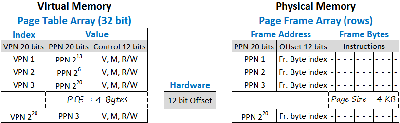
The Offset is implemented in the CPU hardware and is used in the system in various context. The Offset bits are used as an index to sequentially access the bytes in a Page frame. The Offset is therefore a counter which increments in bytes to index into the memory elements of a Page frame. The Page size is fixed by the Offset maxima which sets the upper limit of a Page frame in physical memory. In a Page Table, the Offset bits are used to store process control information as it has no significance in the virtual context.
When a Page Frame array is created in Physical Memory, it is assigned with a 20 bit array address called Physical Page Number (PPN). The Offset defines the Page Frame size which is 2^12 = 4096 bytes = 4KB. While VPNs are consecutive indexes of a page table, PPNs are also consecutive frame address in physical memory. However each VPN is assigned with a random PPN depending on the availability of 4096 consecutive bytes of free memory for loading the frame data.
The address of a physical memory location is formed by concatenating the PPN with Offset. In other words, a physical memory location is specified by the address of an array (page frame) together with the index number (offset) of an element in the array.
Number of Page Frames possible with 20 bits = 2^20
Total Physical Memory that can be occupied by Page Frames = No. of Page Frames * Frame size = 2^20 * 4096 bytes = 4 GB.
Unlike Virtual Address Space where each process can occupy the entire space on its own which is 2^32 = 4GB, the Physical Address Space can be a maximum of 4 GB which has to be ultimately shared by all processes. Sharing require processes to enter the physical memory in batches, get executed by the processor and then exit the memory to make space for a new process. This is further optimised by loading only a part of the process in page table to memory comprising of only the essential tasks which came to be known as Demand Paging and is an improvement on pure virtual paging.
The 4GB address space limitation in 32-bit systems is overcome by a mechanism called Physical Address Extension or PAE. PAE systems are actually 36 bits, meaning that they have 36 physical address lines, capable of addressing 2^36 = 64 GB physical memory. However, processes must run in virtual memory in 32-bit mode to comply with instructions created specific to the platform architecture either in 32-bit or 64-bit. The operating system in turn has to read and write to the physical memory in 32-bit mode, which demarcates the lowest 4GB memory space within the installed RAM (greater than 4GB), as the active region to run processes. The higher region memory being outside the scope of 32-bit operation remains passive, but is usable in the 36-bit (long) mode. When a process ends, the operating system relocate the page frames from the active to the passive memory by switching to long mode and changing the PPNs in the process page table to map to the passive memory. Increasing RAM in effect enhances the capability of the system to cache more processes in passive memory thereby minimising the need for disc paging.
Demand Paging is a memory management technique based on principles that are independent of the system architecture or installed RAM and applies to PAE as well as 64-bit systems.
Demand Paging
The operating system is responsible for managing all information related to a process in a Process Control Block (PCB) within the OS kernel. These are broadly classified as process identification data, process state data and process control data. The process identification data hold mappings between Process ID and Page Table Base Address (PTBA) which is the starting address of a Page Table in the physical memory. Every CPU has a Page Table Base Register (PTBR) which is accessible only to the operating system to store the current page table base address. During a process switch, the operating system simply makes a change of the page table base address in PTBR.
The CPU has a Program Counter which holds the virtual address in 2 parts. The high order bits contain the VPN which is a counter that increments by virtual page number and the low order bits contain the Offset which is a byte counter to index into the memory elements within a page. The VPNs are identical for all Page Tables because the virtual memory addresses generated by the Program Counter is the same for all processes. This Program Counter is driven by the logic set in the CPU hardware.
The Memory Management Unit (MMU) of the CPU first refers to the Page Table Base address in PTBR to access the Page Table in physical memory, and then refers to the VPN part of the virtual address in Program Counter to index into the Page Table and identify the PPN corresponding to the VPN. The MMU generates the physical address by concatenating the PPN with the Offset part of the virtual address in the Program Counter and stores this physical address on the Memory Address Register (MAR) of the CPU. The CPU reads the address in MAR to fetch the instruction from the physical memory and execute it. The Offset in the Program Counter increments to point to the next virtual memory location and the cycle repeats. When the Offset crosses its maximum value (all 1s), the VPN part in the Program Counter is incremented to point to the next VPN in the Page Table.
A process execute by the VPNs arranged sequentially in the form of virtual memory which is translated to PPN by the MMU for accessing the instruction from physical memory.
In the language of the OS software, the processor executes a process by sequentially fetching instructions from the virtual memory, where the virtual memory address indexing the page table array serves as a MEMORY POINTER to the PTE containing the physical memory page address. Thus all memory R/W operations are performed by pointer instructions referenced to virtual memory.
When a process initiates, the operating system creates its page table by mapping virtual addresses to physical address of the process files in hard disc. The OS marks a Valid bit = 1 for Pages in the page table that correspond to tasks that are required to be loaded in memory. Pages that are not to be loaded into memory at the initial stage are marked as invalid with Valid bit = 0. Next, the Page Frames are created on physical memory, and are loaded with codes from the process files in hard disc. Finally the Page Frame address (PPN) replaces the physical address of the page in page table which was initialized with the file location in hard disc. This is the essence of Demand Paging.

Once all Page frames are created and the process is ready for execution, the OS updates the PTBR of the CPU with the Page Table Base address and resets the Program Counter. The MMU indexes into the Page Table and loads the MAR only if the PPN has a Valid bit = 1.
If a fetched instruction is a pointer to another memory location containing the actual instruction, then the MAR is updated to the memory location of the pointer address. The image of PTBR, Program Counter and all CPU registers are saved in memory before the execution jumps to the memory location updated in MAR. On completion of the instruction(s), the return statement reloads the registers with the saved image so that the execution returns to the original virtual address and resume sequential operation. This is called Context switching.
The MMU generates a Page fault if the virtual page address has a missing frame number in the page table Or the frame number does not exist in physical memory Or the physical address is not part of the current working set but is in standby/modified list.
The Page fault invokes the Page handler of the operating system which tries to find a resolution depending on the type of page fault. The Page handler first ensures that the page request is genuine. If it is found to be not genuine, the process is terminated. If it is a genuine request, the operating system determines the missing code/data and loads it from the hard disc to a free location in memory thus creating a new page frame. The new Page frame address is updated on the faulting page in the Page Table and the page is marked as valid with a valid bit = 1. If the Page frame is in standby/modified memory, the MMU has to simply update the frame number on the faulting page which brings the page back from standby to the working set. The Page handler finally returns to the original process resuming execution at the faulting page.
When a process needs to execute a new task, the operating system creates the new task in physical memory and updates one or more VPN of the task initially marked invalid on the Page table with a valid bit, and define its corresponding PPN in the PTE. If this new task is a shared process, then the PTBR is updated with the Page Table Base address of the shared process which triggers the execution of the task. Alternately the page frames of a shared process can also be mapped within the Page Table of another process.
Translation Lookaside Buffer (TLB)
The performance of a Page Table is improved by implementing Translation Lookaside Buffer (TLB) which is a cache maintained on the registers of the processor's MMU, to store the recently used pages of the page table. When the MMU needs to read a Page from the Page Table in memory, it first tries to read it from the TLB by default, which is much faster than reading from the memory. If the Page does not exist in TLB, then the MMU first copies the Page from the page table into the TLB and then reads it from the TLB. The TLB memory is associative meaning that memory elements are addressed by contents (values) rather than an address. Thus both the VPNs and PTEs of a Page Table reside as values in TLB.
The success of the TLB rests on the statistical principle of locality which states that a page accessed recently will be required to be accessed shortly again called Temporal Locality; and page numbers nearby an accessed page has a high probability to be accessed within the next few memory references called Spatial Locality.
Temporal Locality is supported by caching of recently accessed pages in TLB whereas Spatial Locality is supported by Prepaging which is to cache all valid Pages in a Page Table before they are actually requested. Thus on a Page fault, all pages that were earlier part of a working set are added to the TLB instead of only the faulting page. This checks the need to invoke the Page Handler repeatedly for every missing page in the TLB.
When a page is found in the TLB, it is called a TLB Hit and when a page is not found, it is called a TLB Miss. A TLB hit eliminates the need to access a Page Table in memory, whereas a TLB miss incurs a Page Table access in memory. The principle of locality is the cornerstone of TLB success with a hit rate of more than 99%. In other words it means that a Page Table access in memory is required once in 100 times.
Segmentation
Segmentation is a comprehensive memory addressing method by itself and can be implemented independently to directly manage the Physical memory with 16 bit addressing called Real Mode Or implemented as Virtual addressing in 32 bit system architecture called Protected Mode and this can be further combined with Demand Paging.
The earliest memory addressing method was in 16 bit Real Mode, where programs would be loaded directly in the physical memory in segments at fixed locations. The processor would execute the codes sequentially by the address generated by the Program Counter. The Segments started from the lowest address in Code (Text) segment, followed by Data segment, then the Heap segment and the finally the Stack segment at the top address, with a Free memory segment located between Heap and Stack both of which can grow into the Free segment.
The Code segment contains the machine code from the program executable and is read only. The Data segment stores the external data that a program needs to process or compute upon. The Heap segment holds data that are globally available to the program such as addresses of shared processes and Dlls. Stack contains the intermediate results of a process calculation in temporary variables. They also contain parameters passed as arguments to a function and its return values. Further, the highest Stack address is reserved for the Program Counter to store its current address when the program has to jump to another memory location either to fetch data or to execute a subroutine. The return statement in the program loads the Program Counter with the main address stored in the Stack.
With the advent of 32 bit systems, programs were organised in virtual memory to overcome the space limitation imposed by physical memory. Thus many programs could exist on virtual memory but only a few at a time could take up physical memory.
A program is a collection of segments of various size. The free segment was eliminated as Stack and Heap segments could be enlarged dynamically during system runtime.
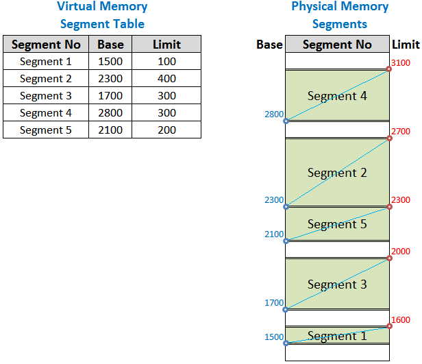
The virtual address space of a process is defined in a Segment Table held in associative memory within CPU by a Segment Table Base Register (STBR). The Segment Table contains a fixed set of Segment Numbers as virtual addresses with corresponding physical address specified by Segment Base, Limit and Segment Protection Information.
The Segment Base is the start address of the segment in physical memory and is the CPU's reference to a segment. The Limit defines the segment size which is variable and depends on the size of the segment defined by the program. The Segment Table therefore defines the virtual memory where each virtual segment number maps to a continuous block in physical memory specified by the Base Address and the Limit.
Unlike the PTBR which holds the address of Virtual memory i.e. the Page Table, the STBR hold the Virtual memory itself i.e. the Segment Table.
A process is ready for execution when all segments of a process are created in memory and the operating system loads the STBR with the segment table.
The Program Counter resets and generates the first virtual address with the high order bits containing the Segment number and the low order bit containing the Offset to index into the memory bytes within the current segment limit. The Offset counter incorporates a logic to check that it does not exceed the Limit defined for a given segment. The MMU reads the segment number in the Program Counter and refers to the Segment table to obtain the Segment Base. The Base address is concatenated with the Offset in the Program Counter to generate the physical address which is stored in the MAR. The CPU fetches the instruction from the memory address in the MAR and executes the instruction.
Since a segment number can define a larger unit of virtual memory than a page, only a few segment numbers is sufficient to constitute a process. The Segment Table size composed of 5-10 virtual segment numbers is considerably less compared to a Page Table size composed of 2^20 virtual page numbers. However a Segment number mapping to a large segment in continuous physical memory locations will cause External Fragmentation resulting in Memory Leakage, when too many free memory slots are lost between segments which fall short in continuity length to allocate to a segment. This happens because, when old processes are removed from memory and new processes are introduced, the new process if larger cannot take the segment space of the old process thereby creating gaps, and if smaller will create free space between segments.
It should be noted that memory leakage is a more general phenomenon which can occur due to factors other than fragmentation, such as bugs in a program.
External fragmentation require compacting of physical memory by repositioning segments or paging out entire segments to hard disc when free memory runs low thus degrading system performance. This is why modern operating systems does not implement memory segmentation which offers too much memory management leverage to programs which has no prior knowledge of the availability of free physical memory in a target system and thus puts up the burden on the operating systems to free up space.
This shortcoming in pure segmentation was sought to be improved upon by combining Segmentation with Demand Paging where each segment is composed of consecutive pages defined in a Page Table with corresponding Page Frames scrambled in physical memory. This achieves to eliminate the source of external fragmentation due to structuring a physical segment in continuous memory locations. Thus we have one segment table per process, one page table per segment. The Segment Table contains the same entries i.e. the Segment number, Base and the Limit. But here the Base refers to a Page Table Base Address (PTBA) in the physical memory and the Limit refers to the number of virtual pages in the page table of a segment.

The Page table entry contains the page frame numbers and process control information. Read/Write protection can be provided in the Segment Table as well as in the Page Table depending whether the protection is required for the entire segment (eg. code segment) or at page level (for read only constant data).
The segment table is located in the CPU's Segment Table Base Register (STBR) in associative memory whereas the Page Table resides in physical memory. Both table information are derived from the Process Control Block in the OS kernel. The Page table per segment has variable number of pages depending on the size of the segment and thus each page table has varying virtual address space built by page units of fixed size.
A process initiates with the operating system loading the STBR with the Segment Table containing the Page Table Base addresses. The Program Counter resets and generates the first virtual address. The highest order bits comprise the Segment number counter, followed by the middle order bits containing the VPN which is a virtual page counter, and the low order bits contain the Offset which is a byte counter to index into the memory elements within a page. The virtual page counter incorporates a logic to check that it does not exceed the Limit (number of pages) defined for the Page Table of the currently executing segment.
The MMU reads the segment number in the Program Counter and refers to the Segment table to obtain the Page Table Base address in physical memory. The VPN part in the Program Counter is then used to index into that Page Table and locate the physical frame number (PPN). The PPN is concatenated with the Offset in the Program Counter to generate the physical address which is stored in the MAR for the CPU to fetch and execute the instruction from memory.
Segmentation with paging eliminated memory leakage due to external fragmentation and the need to compact memory. Segment Limit can be increased dynamically to allow Process growth which becomes easier to manage by simply adding pages to the segment's page table whose page frames gets randomly distributed in physical memory. Sharing and Protection is also more flexible as it can be at the Segment level and also at Page level. Sharing of data or code of a process is the sharing of its segment number which is sharing of the Page table for that segment.
On the downside, segmentation leads to slower address translation due to two level of addressing, which reduces performance. However this is largely controlled by setting up the Segment table in the CPU register and Page table in the TLB. Context switching is heavier in segmented systems since both the page table and segment table need to be saved during each context switch.
As we shall see in the following section, Page Table size becomes enormous in 64 bit system and so memory addressing by Segmentation with Paging is not viable beyond 32 bit systems. Thus 64 bit processors support segmentation in 32 bit mode but not in the 64 bit mode.
Size of Page Table
First a quick recapitulation of terms related to Page.
Address Space = Virtual Memory size available to a process.
Page = The unit of virtual memory allotted to a process.
Page address = The virtual address used by a process to access a page.
Page Size = Number of memory bytes required to compose a Page Frame in physical memory. The Page Size is fixed in the Program Counter of the CPU.
Remember !! A Page is the operating system's ID of a Page Frame in physical memory, and this Page ID exists in the form of a virtual address on a Page Table.
Page Table = A map of virtual page addresses with its corresponding page frame address in physical memory. Page Table exists on the Physical Memory.
Page Table Entry (PTE) = Physical address and other information entered in a page table corresponding to each virtual page address of a process.
Page Table Size = Count of VPNs (=PTEs) * PTE size.
Let us calculate the Page Table size for 32 bit and 64 bit systems with 4KB page size. The size of this Page table depends on the system's address bit architecture (32/64 bit) and the Page size.
32 bit system
PTE size = 32 bits = 4 bytes
Page Size = 2^Offset = 2^12 bytes = 4KB.
Page Table Size = Count of Virtual Pages in a page table * PTE size
Page Table Size = (Address Space per Page Table / Page Size) * PTE size
= (2^32/2^12) * 4 bytes
Page table size = 2^20 * 4 bytes = 4 MB.
4MB is the maximum space that a single process can occupy in the Virtual Memory. You can check the number of running processes from Task Manager > Performance tab > CPU tab (left section) > Processes (right section). Assuming an average of 100 running processes, the sum of all page table size = 4MB * 100 = 400 MB.
64 bit system
64 bit systems have a theoretical address space of 2^64 = 16 Exabyte.
This is much beyond the scope of system hardware commercially available as of now. So 64 bit systems are scaled down to operate in 48 bits with an addressable space of 2^48 = 256 TB.
So, PTE = 48 bits = 6 bytes.
Page Size = 2^Offset = 2^12 bytes = 4KB.
Page Table Size = Count of Virtual Pages in a page table * PTE size
Page Table Size = (Address Space per Page Table / Page Size) * PTE size
= (2^48/2^12) * 6 bytes
Page Table Size = 384 GB.
This is the Page Table size of a single process irrespective of the real size of the process.
Page table was of manageable size for 32 bit systems but assumes a gigantic value for 64 bit systems that defeats the very implementation of virtual memory. While special mechanisms such as Multi-level Page Table and Inverted Page Table evolved to reduce page table size in 32-bit systems due to prevailing RAMs of low capacity, it became imperative to implement these special mechanisms in 64-bit systems to bring down the gigantic Page table size, even though large capacity RAMs in GBs became the standard.
Optimizing the Page Size
In the above 64 bit example if we use an Offset of 21 bits, Page Size = 2^21 bytes = 2 MB,
Page table size = 2^48 / 2^21 * 6 bytes = 768 MB.
All tasks of a process are allotted to memory by a fixed or variable number of pages. In variable page allocation as in segmentation, when binary codes and data fill out the page frames in a physical segment, we can expect on an average that the uppermost page frame in a segment to remain 50% free. So larger the Page size, the more will be the unused space in the uppermost page of a segment. This level will vary from process to process but the sum of all free and unused spaces leads to Internal Fragmentation. It has been found that Page size in the range 1KB to 8KB provides an optimal trade-off between Page Table size and internal fragmentation.
If we assume 100 running processes each with 5 segments, then the approximate internal fragmentation for 4KB and 2MB page size will be (0.5*4KB)*5*100= 1MB and (0.5*2MB)*5*100= 500MB respectively. Page size is set in the CPU hardware depending on the system architecture and size of RAM installed.
Internal fragmentation will be even more in systems with fixed number of page allocation, where multiple page frames in the upper region of Page Table can go unutilised, for processes having memory requirement much less than the space allocated by the page set.
However when a server is meant to run a few dedicated Processes which are particularly large, a 2MB page implementation would result in significant performance gain outweighing the memory leakage due to internal fragmentation.
Multi-level Page Table
We know that,
Size of any Page Table = Count of pages (height) * PTE size (width)
= 2^Table index bit size (page numbers) * PTE size
= [2^Table bit size / 2^Offset] * [Operating bit size/8]
In 64 bit systems, the basic Linear Page Table assumes a gigantic size because the Table bit size assumes the value of Operating bit size. The purpose of Multi Level Page Table is to break the Linear Page Table into multiple Page Tables having the same Page Size (2^Offset) but smaller Count of pages per table (or smaller Table index bit size used for allocating page numbers) and therefore smaller Table size. The size of these multiple Page Tables will essentially add up to the size of the Linear Page Table. However, each of these smaller Tables represent a process and so the Operating System can choose to selectively load Page Tables to memory as per memory availability and page out a Table to Hard Disc when the process become inactive or is terminated.
Multi Level Page Tables are arranged in hierarchical groups, such that each entry on a page table identifies another page table down the hierarchy forming a tree of page tables. The last level in the hierarchy contain the process Page Tables while the ones higher up in the hierarchy, helps to identify the process table at the end of the tree.
Increasing the number of hierarchical levels is aimed at further splitting the Page Count (i.e. Table index bit size used for allocating page numbers) of the Page Table structure at the last level in order to reduce the process table size, but at the expense of increasing the count of process tables at the last level. This allows the Operating System to gain finer control for allocating page tables to physical memory. However increased number of levels also increases the number of indexing required to identify the process page table and this becomes less efficient but for the TLB which helps to speed up the indexing by caching the address translation tables.
Let us consider a 2-level Page Table in a 64 bit system with 4KB Pages.
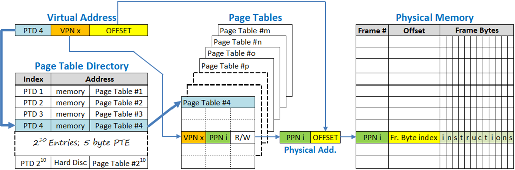
The address space are split into 3 fields: A Page Table Directory containing Page Table Base Address of all processes (highest order bits) + one Page Table per process (middle order bits) + Offset for the Page Tables (lowest order bits).
We have, Offset = Log 2-base (4KB Page Size) = 12 bits.
As in 32-bit architecture, let each process have a Page Table with 20 bit VPN, 12 bit Offset and we have a 10 bit Page Table Directory (PTD) to account for 2^10 = 1024 processes.
Thus, Address Space (42 bits) = PTD (10 bit) + VPN (20 bit) + Offset (12 bit).
The virtual address sequence in the Page Table Directory (PTD), the virtual address sequence in the Page Table (VPN) and the Offset comprise three distinct counters generating the complete virtual address within the Program Counter.
The MMU of the processor uses the highest 10 bits of the virtual address to index into the Page Table Directory and determine the page table base address. It then uses the next 20 bits of the virtual address to index into the Page Table and look up for the Page Frame address in physical memory. The lowest 12 offset bits in Program counter is used to index into the Page Frame and locate the instruction.
When the Offset reaches its maxima and resets to zero, the VPN gets incremented in the program counter. When the VPN crosses its maxima and resets to its initial value, the PTD increments.
The size of a 42 bit Linear Page Table
= Count of pages in Page Table * PTE size
= (Address Space/Page Size) * PTE size
= (2^42/2^12) * 5 bytes
= 2^30 * 5 bytes = 5 GB.
This is the Page Table Size of a single process. So for a typical of 100 processes the memory requirement is 500 GB!
When the 42 bit address space is split into two or more levels of indirection, the 30-bit Table index of its Linear counterpart used for allocating page numbers, gets distributed on the multi levels (10 bit + 20 bit), while the Linear Table's Page Size (4 KB) and PTE (5 bytes) remains constant for all table across levels. Count of Page Tables at any level = Sum total of Page Count of all tables at preceding level. Thus by our example, we have 1 PTD with 2^10 pages and therefore 2^10 Process Tables.
So the Total Size of 42-bit Multi Level Page Tables:
= (Size of PTD) + (Count of Page Tables * Size of each Pagle Table)
= (Count of Pages in PTD * PTE) + (Count of Page Tables * Count of VPNs * PTE)
= (2^10 * 5 bytes) + (2^10 * 2^20 * 5 bytes)
= 5KB + 1024 * 5MB = ~ 5 GB.
However here it implies that the Page Table Size of a single process is 5MB and 5GB is that of 1024 processes. So for a typical of 100 processes the memory requirement is 500 MB.
The essence of Multi Level Page Table is to control the Page Table occupancy in Physical Memory by retaining only the Page Tables of current processes in the Physical Memory while paging out the Page Tables of non-current processes into the Hard Disc. Since the Page Table Directory (5 KB) is nodal for all process management, it must remain in Physical Memory at all times. The PTEs in the PTD are the Page Table Base addresses which may refer to a memory location Or a Page File location in hard disc for Page Tables that have been paged out.
The operating system will try to retain all created Page Tables in Standby list in physical memory. If the free memory level runs below a certain threshold, some of the Page Tables in Standby will be Paged out to Hard Disc and those Standby list will be released to Free memory.
System designers control the size of Virtual Memory by limiting the virtual address space and/or defining more than 2 level of Page Tables to span the address space and/or setting an appropriate Page Size in the hardware. For example, Page size of 2 MB is used to gain system performance when large processes need to run on the target system.
We have, Virtual Address Space = count of Page Tables * count of pages in a Page Table * Page size.
When Virtual Address Space and Page size is constant, the count of Page Tables becomes inversely proportional to the count of pages in a Page Table. Increasing the number of levels beyond 2 level does not necessarily reduce the overall size of all Page Tables. What is does, is to reduce the size of a Page Table and increase the count of Page Tables. This allows the Operating System to gain finer control on physical memory utilisation by the virtual memory (page tables).
But for the TLB, a multi-level page table would have had considerable performance loss, due to multiple indexing involved through two or more levels of page tables to locate a page frame in physical memory. The TLB helps to eliminate about 99% memory referencing by storing a cache of the Page tables from memory into its registers.
In the language of the operating system software, the virtual memory address is a pointer to the physical memory address, which in the case of multi-level page table resolves through a chain of indirection where one virtual address is a pointer to another virtual address spanning across address tables, leading to the physical memory address at the final level.
Inverted Page Table
The first Windows 64-bit Server solution was built on Intel Itanium 64 bit platform which implemented the Inverted Page Table (IPT). IPT initially remained a frontrunner for 64 bit systems particularly in UNIX and Solaris. However Multi Level Page Table became the preferred choice for Windows as it embraced 64 bit technology to develop into the future for both desktops and servers.
The Inverted Page Table is a strategy to reduce page table size by defining a Page table where the address space refers to the physical address space of RAM instead of the virtual address space. This makes sense on server systems having large amount of installed RAM to meet the demand of all running services. While a normal Page Table is indexed (addressed) by VPN to the PTEs containing PPN, the Inverted Page Table is indexed by PPN to the PTEs containing VPN - thus limiting the virtual memory space to the physical memory space.
In a normal implementation of virtual memory, every process has its own page table with each page table having the same set of virtual addresses, and so the virtual memory space is variable depending on the number of running processes. In an Inverted Page Table, the virtual memory space is fixed by PPNs indexing a Single Page Table shared by all running processes, whose VPNs are randomly distributed in the table. Allocating a process in continuous pages will lead to internal fragmentation of the Page Table itself !
Since the virtual address set has to be same for all processes fixed in the Program Counter, a process identifier (PID) is required in each PTE of the IPT to identify the VPNs corresponding to a process, as processes can no longer be distinguished by individual page table base address. The PID is 2-byte long and is part of the process control information in the PTE.
Shared processes are not mapped within the virtual address set of a process, but are executed by a call-return statement to the shared process existing in the IPT.
An Inverted Page Table (array) first gets created with the PPN as index, which is then updated by the PID and VPN, and finally the Page Frames are created in physical memory in the index (PPN) sequence of the Inverted Page Table.
Let us calculate the Inverted Page Table size for a 64 bit system with PTEs comprised of 40 addressable bits (5 byte) + 2 byte Process ID + 1 byte for Control information, 4KB Page Size and 32 GB RAM.
Address Space = 32 GB RAM = 2^35 bytes
PTE size = 5 + 2 + 1 bytes = 8 bytes.
Page Size = 2^Offset = 2^12 bytes = 4KB
Page Table Size = (Address Space / Page Size) * PTE
= (2^35/2^12) * 8 bytes
Page Table Size = 2^23 * 8 = 64 MB which is only 0.2% of the 32 GB RAM.
An Inverted Page Table is an array whose index corresponds to the Page Frame Address in physical memory (PPN) and PTEs are a reverse mapping to the Virtual Page Address (VPN) of the process owning the frame. This does not change the principle behind the virtual memory operation, where the virtual memory address serves as a memory pointer in OS instructions to access the physical memory.
In the light of above it implies, that instead of indexing into a normal page table by the VPN generated in the Program Counter, the VPN and its corresponding PID has to be searched from the PTEs of an IPT in order to obtain the PPN. The search time in locating the PID & VPN is substantial making this an extremely inefficient proposition.
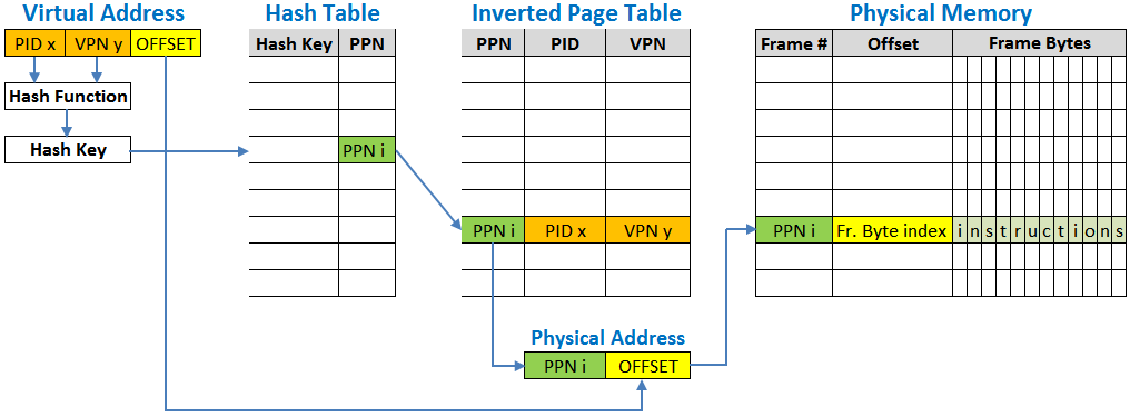
The search function is therefore eliminated by a Hash Table which is an array whose index is formed by reducing the PID & VPN by a hash function into a hash key, while the array entries correspond to the PPN. Thus the Hash Table is in essence a normal Page Table derived from the Inverted Page Table. The time and space overhead in creating an extra Hash Table, far outweighs the otherwise performance loss in directly using the IPT.
A task executes when the operating system changes the PID in a CPU register which resets the VPN in Program Counter. The processor use the hash function to generate a hash key from the PID & VPN, and index into the Hash Table with the hash key. The PPN value stored at this index of the Hash Table is used to further index into the Inverted Page Table for its PTE. If the PID & VPN in CPU matches with the PID & VPN at the PTE of the Inverted Page Table, the PPN is used to generate the Physical address by concatenating it with the Offset in the Program Counter. This physical address is used to fetch the process code and data for execution. If no match is found between the CPU data and PTE, a hash collision resolution technique is used to determine the PPN, by chaining hash entries to point to other entries in the hash table. A pure search of the PTEs in the Inverted Page Table can alternately be enforced.
The Hash Table eliminates the need of a table search but at the cost of two indexing – one in the hash table and the other in the page table. The use of Translation Lookaside Buffer (TLB) is particularly necessary to improve the performance of an Inverted Page Table by serving as the first level map for virtual to physical memory translation. On a TLB miss, the Hash table is used as the second level map, and finally a Page Handler of the operating system is invoked for resolution of a Page fault.
All these jugglery is just to ensure that least amount of physical memory is invested on the Page Table (virtual memory) which manages that very physical memory present as a limited resource.
Concluding Remarks
RAM evolved to serve as a buffer between the low speed magnetic hard disc storage and the high speed processor. RAM can get obliterated in future if hard disc speed can attain the speed of RAM. Currently, the storage technology has advanced to Solid State Drives (SSD) and SD cards delivering significant speed, robustness and miniaturisation necessary for mobile devices. But these drives cannot effectively replace RAM because of their limited write cycle endurance defining its life span. As a storage device, SSDs has an inbuilt controller which distributes the write cycles uniformly to all its usable space to improve the life span to a minimum of 5 years. However this strategy will not extend the life of SSDs if made to emulate as RAM, because write cycles are overwhelmingly large in RAM where objects like webpage, apps and data are created or edited all the time. In fact, the RAM acting as a buffer has to write all objects that are read from storage locations, be it in web/network/local storage.
There is yet another possibility of RAM eventually getting merged with the processor cache, when technology has sufficiently advanced to produce highly miniaturised and low power consuming memory chips, viable to attain the saturation size in system design.
In the present scheme of things, the purpose of memory to run processes, remains distinct from the purpose of hard disc to store data and send stored process files to memory through Device I/O operation.
The exception is the page file on hard disc which is mapped into the memory address space and acts as a secondary cache when memory demand of processes run higher than the installed memory. Due to slow response time of the hard disc, the page file is never a true replacement for RAM and is applied only as a contingency measure to free up memory space. Increasing the size of page file will not enhance the performance of the system.
The 4GB memory limit and 2TB storage space limit in 32-bit systems, makes a quantum leap in 64-bit systems, which is way beyond the maximum capacity of RAM and Hard Disc that can be currently supported in an high end system. Thus 64-bit systems remain vastly open-ended to allow for all future developments in technology over the next decades.
A short write-up on Device I/O and Disk access is available at the following link:
Regards,
Sushovon Sinha